
Drake R4B recapping, July 24, 2010
Introduction
Click on the photos for a larger version, depending on your browser maybe even click again for still larger.
Recapping my R4B using the Hayseed Hamfest kit had been on my list of things to do for some time. Hayseed had some supplier problems and hence the kits were unavailable for a while, so when they became available again I got the kit. I have to say at the onset that I had a tougher time than I think most will, because while I knew the previous owner had done surgery on the R4B, I didn't realize the full extent.
Thanks to everybody on the Drake list who helped me through the confusion, especially of course Garey K4OAH, whose excellent Drake service guides are a must-have !
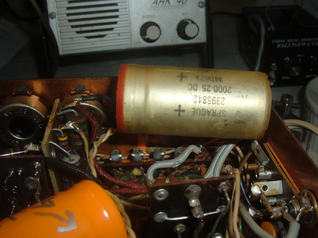
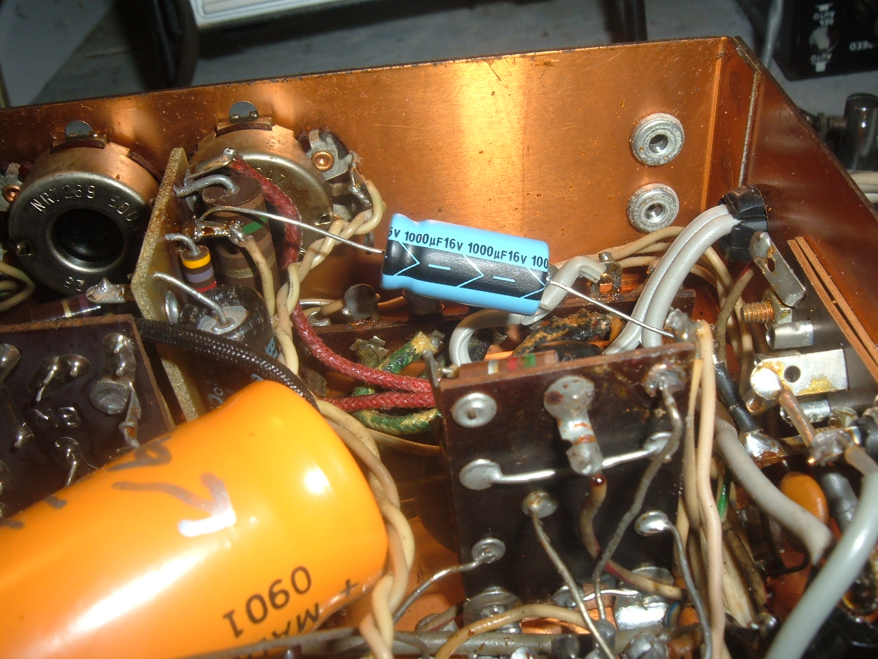
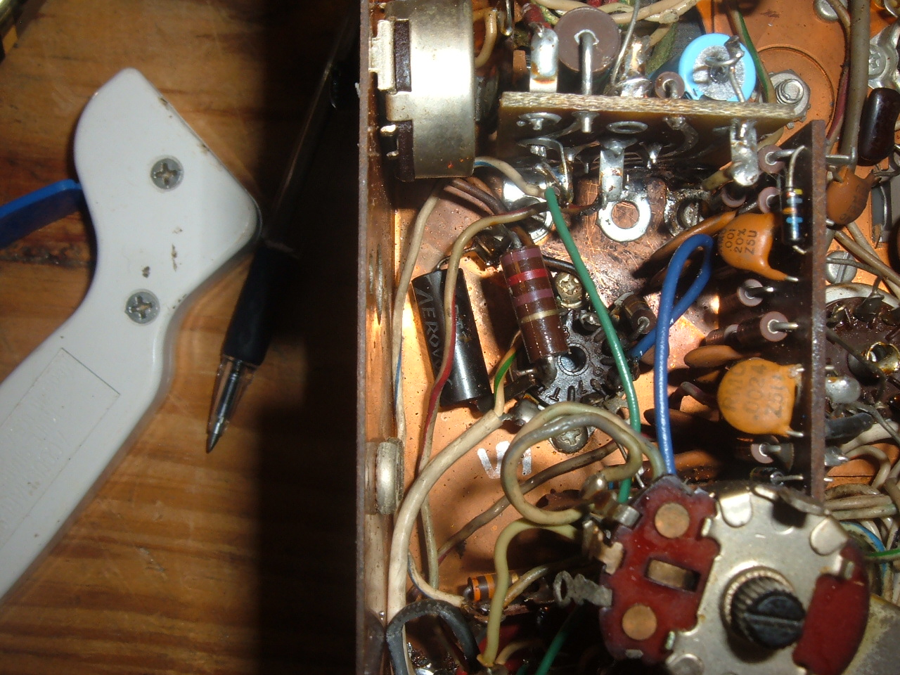
We had thought that the previous owner had simply stalled the real repair by tacking an additional cap under the chassis. But, the "diagonal one" (see above pic) was not in parallel with C90C, but rather he had replaced the 4-section can with a new 3-section can, plus added the "diagonal one" underneath for the third 100uF section because he couldn't find a 4-section can. If I had to guess, maybe 15 years ago ? So I assumed the can on top of the chassis was the original, but it was not. This led to some confusion, which was eventually resolved.
First to be tackled - C192, 1000uF 15VDC, the replacement is 16VDC.
Next was C190, 200uF 6VDC, the replacement is 220uF 6.3VDC. This is mounted on Board 8, so the board has to be un-mounted to get at the cap.

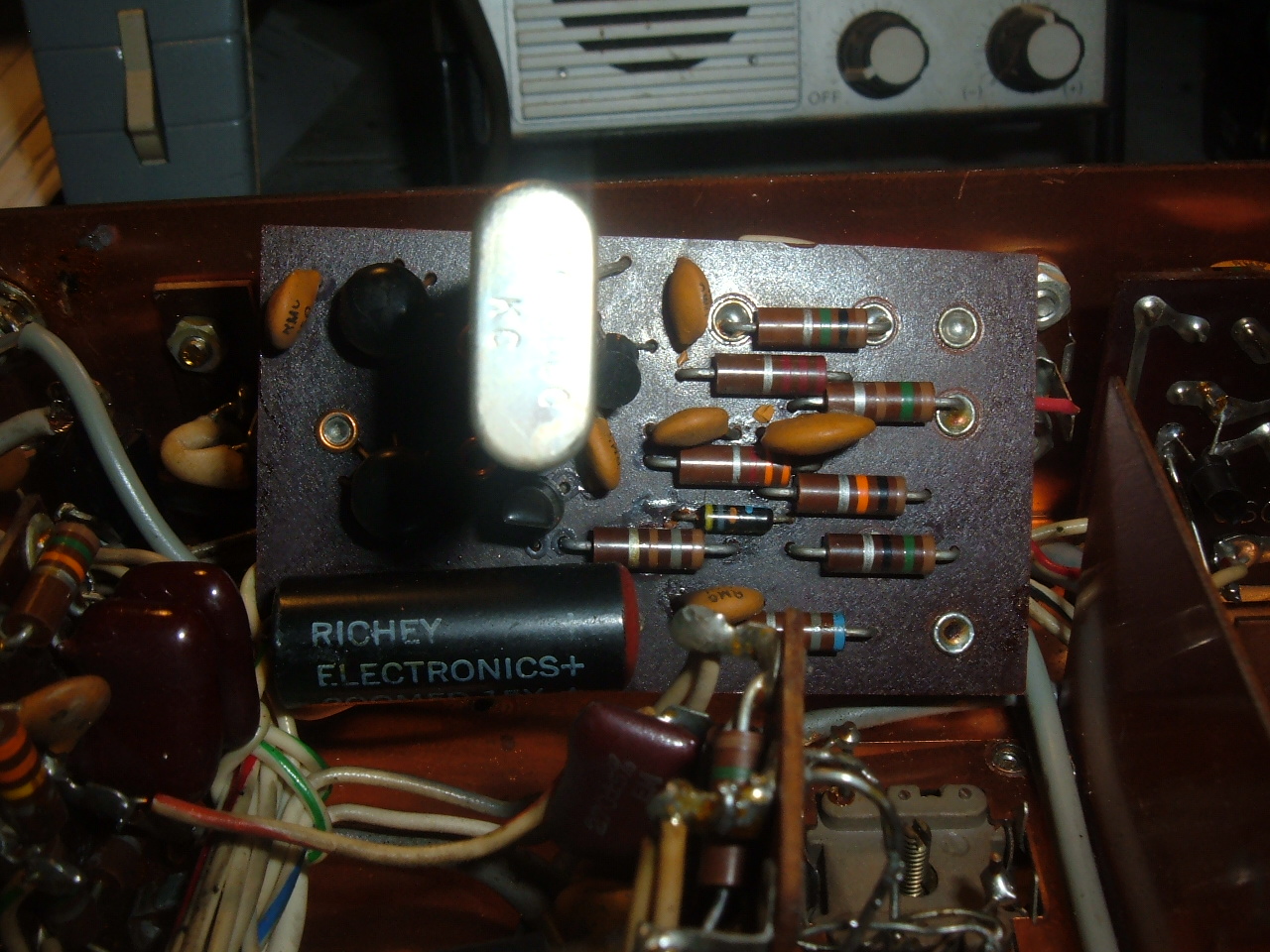

Next was C91, 8uF, 150VDC, the replacement is 10uF, 200VDC. This is mounted on Board 5.

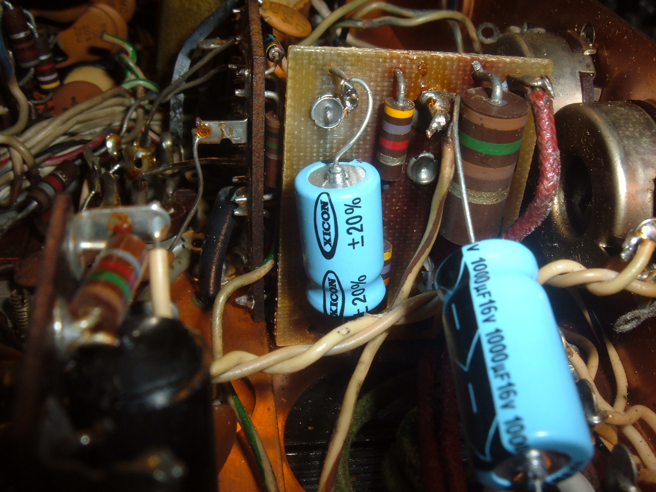
Next is C176 10uF 25VDC, the replacement is 35VDC. (Note there is one more 10uF, on board 2, but it is a tantulum or something, not an electrolytic, so it was not a part of this job.) In Garey's guide, this is located "chassis left side C", Figure R13.
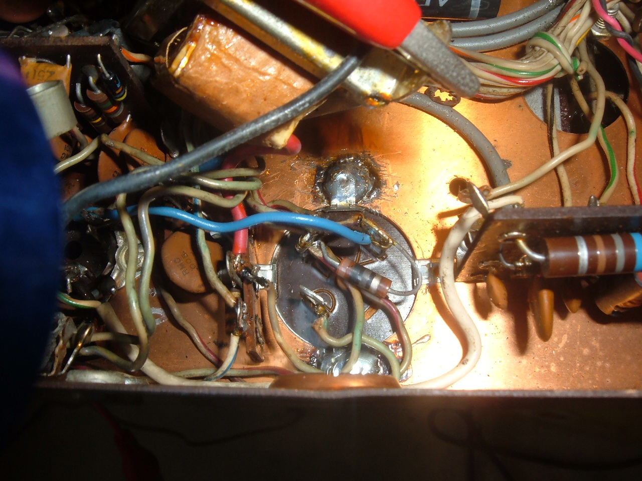
R42, the anti-Vox pot needs to be lifted out to get at it. Carefully pry the tabs holding it in place, you don't want them to snap off.


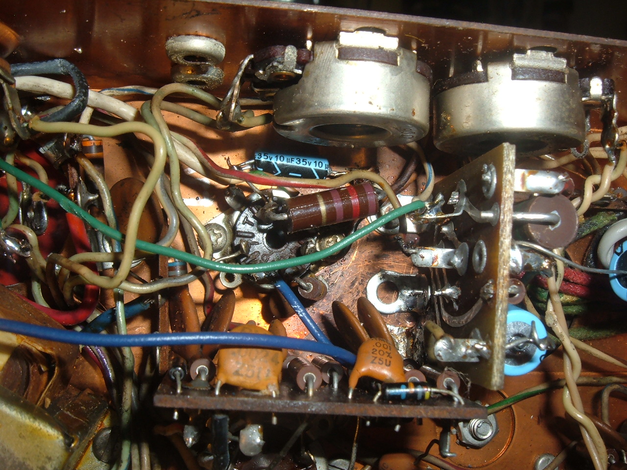
Next is the can, C90A 20uF 200VDC, the replacement is 22uF 250VDC. C90B, C90C, C90D 100uF 200VDC, the replacements are 250VDC.
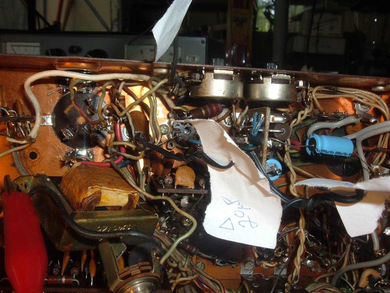
The audio transformer needs to be lifted out of the way to get at stuff. Also, in disconnecting the wires, I labeled them for future reference. Also please note that these photos won't be quite right because as noted earlier, the previous owner had replaced the original 4 section can with a 3 section can. Removing the can is a chore. I bought a new 100watt iron for this project, could have used a 150 or better but then again those might have larger tips and be hard to position without burning neighborhood parts. When I had it just about unsoldered, from the top of the chassis I took a right-angle screwdriver and a small hammer, inserted the screw driver blade under the can by the tab, and tapped it with the hammer until it came loose, that worked well.


For testing power supplies, I personally am a coward, especially when higher voltages are involved, like in the AC4 recapping. So instead of feeding the item 120VAC right off, I step it down to 12VAC using a filament transformer, which itself is behind an isolation transformer. Then I take voltage readings and just multiple by 10. Then if it seems OK I try it out full voltage.

CONCLUSION - A noble project. If part of C90 goes it could take out other hard to replace parts, so this is probably something that should be on your project list. Hayseed Hamfest is performing a great service by making these kits available !
Oh, my crystal calibrator signal is much better now, plus the S-meter seems more responsive than before.
Chuck, K1OM, Alachua, Florida